

- Blog
- 7 Jul 2025
Understanding Carbon Fiber Orientation in Composites
Carbon fiber composites are widely used in industries like aerospace, automotive, and healthcare because they offer high strength and low weight. One of the most important factors affecting their performance is carbon fiber orientation—the direction in which the fibers are arranged within the material. This orientation directly influences how the composite behaves under stress, how it bends, and how long it lasts. From carbon fiber structural reinforcement in buildings to lightweight components in dental tools, understanding fiber orientation helps engineers and technicians design stronger, more reliable products.
What Is Carbon Fiber Orientation?
Carbon fiber orientation refers to the direction in which carbon fibers are placed inside a composite material. These fibers are very strong along their length, so the way they are aligned affects how the material handles force. For example, fibers placed in one direction will make the part strong in that direction, but not as strong in others.
In composite design, engineers choose fiber directions based on how the final product will be used. If a part needs to resist bending or stretching in different directions, the fibers are arranged in multiple angles. This careful placement is key to making the material strong, light, and reliable.
Orientation can be straight, angled, or part of a woven pattern. Each type has its own purpose and performance. Knowing the right orientation helps improve strength, reduce weight, and ensure better results in real-world applications.
Why Carbon Fiber Orientation Matters
The performance of a carbon fiber composite depends not only on the material itself, but also on how the fibers are arranged. This is why carbon fiber orientation is so important. When fibers are aligned correctly, the composite can handle more stress, resist cracks, and stay strong over time.
For example, in the prepreg production process, fibers are carefully placed to match the shape and purpose of the final part. If the orientation is wrong, the product may become weak in certain directions or fail under pressure. That’s why engineers plan the fiber layout based on how the part will be used—whether it needs to bend, carry weight, or handle repeated motion.
Correct orientation also helps reduce waste and improve safety. In industries like aerospace or health care, even small mistakes can lead to big problems. With the right fiber direction, parts become more efficient, last longer, and meet high-quality standards.
Common Types of Fiber Orientations
There are different ways to arrange carbon fibers inside a composite, and each type of carbon fiber orientation affects how the material performs. Depending on the design, fibers can be placed in one direction or at several angles to meet the needs of the final product. Below are the most common orientation styles used in composites.
0°, 45°, 90°, and ±45° Orientations
These are the basic angles used in composite layering.
- 0° orientation means the fibers run straight along the length of the part. It gives high strength in that direction.
- 90° orientation places fibers across the part, adding stiffness in the opposite direction.
- 45° and ±45° orientations help the part resist twisting and diagonal forces. These angles are useful when a component needs to deal with complex loads or vibrations.
Using a combination of these angles allows engineers to control how the composite behaves under different types of pressure.
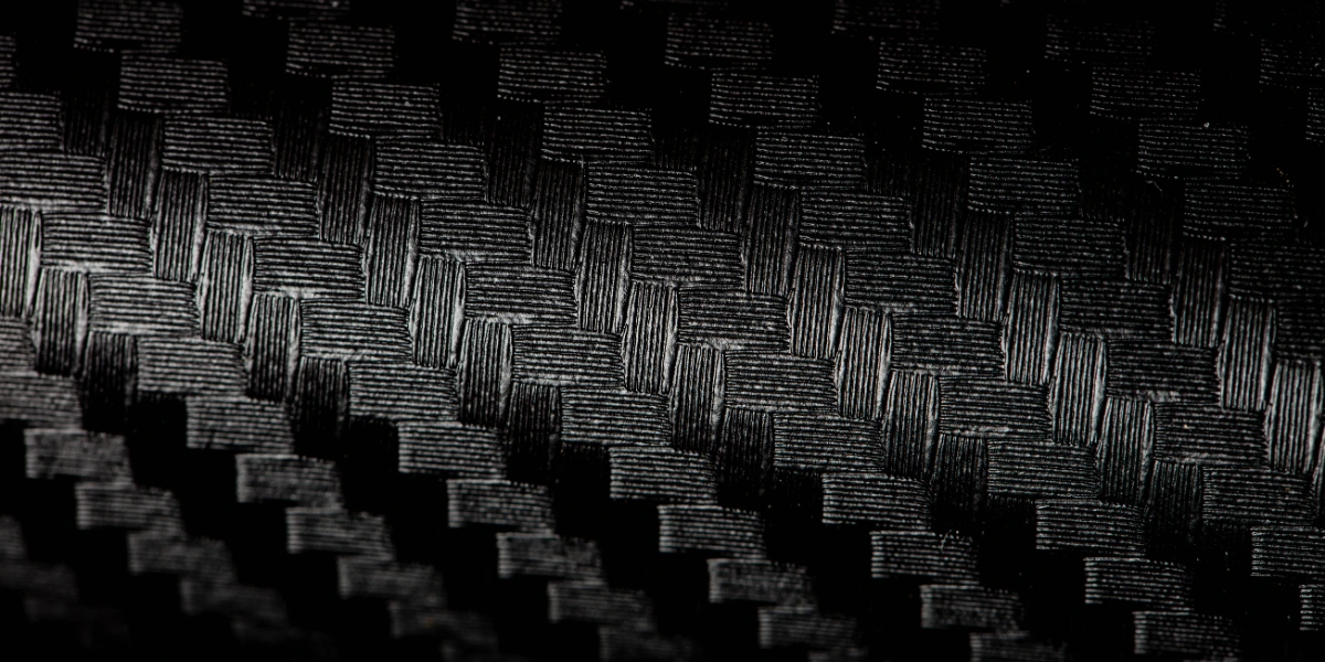
Woven Fabrics vs Unidirectional Tapes
There are two main forms of carbon fiber material: woven fabrics and unidirectional (UD) tapes.
- Woven fabrics have fibers crossing each other in patterns, like a fabric weave. They offer good strength in two directions and are easier to handle.
- Unidirectional tapes have all fibers aligned in one direction. This gives high strength in that specific direction, making them ideal for precision designs—especially in automated fiber placement systems where layers are applied with accuracy.
Each type has its own benefits, and the choice depends on the required strength, flexibility, and shape of the final product.
Quasi-Isotropic and Anisotropic Layups
A quasi-isotropic layup means the fibers are placed in multiple directions (like 0°, ±45°, and 90°) to give balanced strength in all directions. This type of carbon fiber orientation behaves similarly to a metal, which is strong no matter how force is applied. It is useful for parts that face complex or unpredictable loads.
On the other hand, an anisotropic layup focuses strength in specific directions. This is useful when the part will face stress from a known direction, like in aerospace wings or bike frames. While it saves weight, it must be designed carefully to avoid weak spots.
Understanding these orientation types helps engineers make better choices when designing parts with high performance and reliability.
Design Considerations and Challenges
When designing with carbon fiber composites, choosing the right carbon fiber orientation is one of the most important steps. The fiber direction must match how the part will be used—whether it needs to bend, carry weight, or resist twisting. If the orientation does not match the load path, the part may fail, even if strong materials are used.
Engineers must also think about the shape of the part, how it will be manufactured, and which fiber material to use—woven or unidirectional. For curved or complex shapes, orientation becomes harder to control. During the prepreg production process, each layer must be placed carefully to avoid gaps, wrinkles, or weak areas.
Another challenge is balancing performance with cost. Adding fibers in many directions improves strength but can increase material use and production time. Choosing the right carbon fiber orientation is key to optimizing both strength and efficiency. It’s also important to keep the total thickness low to save weight—especially in industries like aerospace and automotive.
Finally, the design must consider real-life conditions. Temperature changes, vibration, and repeated stress all affect how the composite will perform over time. Choosing the right orientation helps reduce these risks and create safer, longer-lasting products.
Tools and Techniques for Controlling Orientation
Controlling carbon fiber orientation during production is key to making strong and reliable composite parts. To do this, engineers use a mix of manual and automated methods, depending on the complexity of the part and the required precision.
One common technique is hand lay-up, where technicians place each layer of fiber by hand. While this allows flexibility, it requires skill and close attention to avoid mistakes like fiber misalignment or air pockets.
For higher accuracy and speed, many manufacturers use automated fiber placement (AFP) systems. These machines place fibers in exact positions using computer-controlled heads. AFP allows for complex shapes and consistent quality, especially when using unidirectional tapes. It’s widely used in the aerospace industry and other fields where precision is critical.
Other tools include cutting machines, lay-up templates, and software that simulates fiber paths. These help designers plan the best orientation layout before production begins. Monitoring tools, like sensors and cameras, also help ensure that each fiber layer is placed correctly during the process.
By using the right tools and techniques, manufacturers can control carbon fiber orientation with high accuracy. This leads to better performance, fewer defects, and more efficient use of materials.